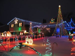
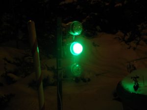
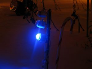
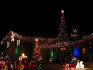
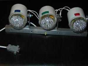
Here’s a how-to of how I created our LED MR-16 spotlight holders. I got a lot of inspiration from this page and on the PlanetChristmas, forums, and would like to thank everyone who helped inspire this project. I decided to change things up a bit, mainly to keep costs down. At least at the big box stores, plumbing fixtures can be expensive. I didn’t want to pay $5-10 per light (not including the LED bulb) and figured there had to be a better way to get the same functionality for a lower price.
My main cost-saving trick was twofold: Firstly, I used PVC pipe for the majority of the body of the lampholders. Many of the other options used some sort of PVC fitting instead, which tends to cost $1.50-$3 for the correct sizes. On the other hand, PVC DWV pipe is dirt cheap. I paid $3.50 for enough PVC to do about 48 fixtures. Secondly, for the bottom of the fixtures, I discovered what’s called a “rough-in cap” or “test cap”, and instead of $1.50 for a pressure-capable schedule-40 fitting, these cost 25 cents each (see below) and seem to work beautifully.
Before we go any further, some disclaimers: Although we used these fixtures in our display for a number of years, I cannot guarantee that they will work in your situation. Furthermore, if you follow these instructions, you do so completely at your own risk. I can’t be held responsible for anything that comes from anyone attempting to do something with these instructions.
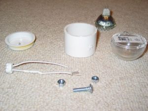
Above, you see all the parts you need to make the basic LED enclosure. The items needed were:
- An MR-16 LED in the color of your choice
- An MR-16 Lampholder. These were purchased from Wirekat Enterprises, along with the LED lights themselves. Resistors are shipped with the lamps, which will help them dim properly with the LOR DC controller board. Prior to this picture, the resistor was spliced into the lower lead of the lampholder, and covered with heat-shrink tubing.
- A 2″-long section of 2″ plumbing DWV plumbing pipe. I purchased a 4′ section from Lowes for something like $3.30, and have enough left over to do many more such fixtures.
- A 2″ “test plug”, also called a “rough in knockout”. My initial prototype used one purchased at Lowes for 50 cents. Then I found out that Home Depot carried them for only 25 cents (cha ching!), but in bright yellow. I simply sprayed them white. If you’re planning on painting yours black (I’m not) then color won’t matter anyway. These are significantly cheaper than the ‘real’ plumbing end-caps (they cost about $1.50 a pop).
- A 60mm acrylic fillable ornament. I got mine at Michaels for 99 cents each, and each one makes two fixtures so cost per fixture is about 50 cents. You can get them cheaper on line, but for my volume, shipping killed the deal.
- A 1″ long, 1/4″ carriage bolt, and two nuts.
- We’ll also need some aluminum stock — see below for details.
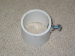 The first step is to drill a hole in the side of the PVC pipe, roughly centered, and thread the carriage bolt through it. Then thread on a nut, and crank it nice and tight with a wrench. This will pull the square part of the carriage head into the PVC. For now, you can simply thread the second nut on loosely.
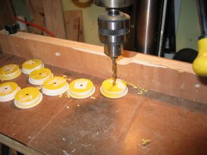 Next we take all the plumbing caps and drill a hole in the center of them. I used a drill press which made it go very quickly — if you’re drillpress-less, a hand drill works too. I used a 15/64 bit which was about as small as I could thread the two wires (with the resistor bulge) through easily
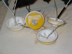 Next thread a MR-16 socket through the hole, and then secure it with hot glue. Press down on a hard surface until the glue sets. I then spread the wires and put a bulge of glue on the bottom as well. We want these puppies weatherproof.
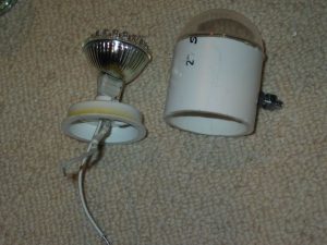
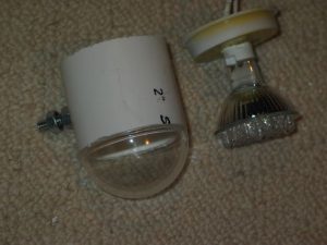
The next step is to attach the dome to the top of the pipe. The dome is 1/2 of the acrylic ornament. Carefully remove the hanging loop from the ornament-half, then run a generous bead of hot glue along the top of the PVC pipe. As fate would have it, the 60mm ornament lines up almost perfectly with our 2″ DWV pipe. Once that set up, I ran another generous bead of glue along the outside seam. Again, we want these puppies to shed water like a good hunting dog. At this point, you can attach the bulb if you’re so inclined.
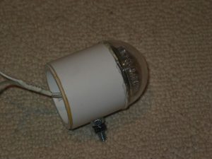 Now you can fit the base into the upper part, and you get a cute little bullet-like light fixture! At this point, DON’T do anything to seal the bottom to the top yet, just friction-fit it for now, and be careful handling them.
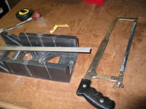 We will now create the L-brackets which will support our lights. One can buy L-brackets, but they’re expensive (at least $1 a piece) and we’d have to drill our own holes in them anyway. To do this “cheap but effective” we’ll need to make our own. To do this, I used aluminum bar stock, available at Home Depot for about $5 for a 4′ length. Each fixture needs 4″ so you can get 12 fixtures out of one such bar-stock. I used aluminum because it’s corrosion-proof, looks nice, and easy to work with. If you’re willing to put up with steel, you can get by about 20% cheaper. You can also no doubt find a cheaper source than Home Depot, but I wasn’t willing to chase all over town for the volume I needed. As noted above, you want to cut each piece to 4″ long. I lack a good power tool for doing this, so I used a crappy old miter box with a hacksaw.
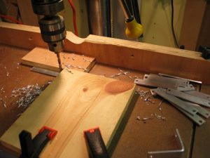 Next you want to drill a 1/4″ hole in both ends of each piece. Drill it as close to the end as possible, but far enough so that there’s enough metal on all sides of the hole to be strong. If you have a drill press, it’s worth the time to set up a positioning jig, as I did, if you’re making more than a couple of these. But watch out — the metal filings like to jam up your jig and will throw off the holes if you’re not careful to keep them out of the way. If you have to hand-drill these, start with a scratch awl to center the hole and work carefully.
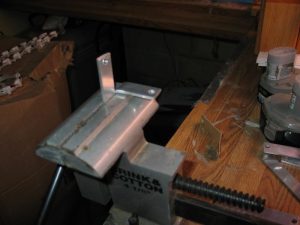 Next we move over to the bench vise to bend the L’s into their final shape. On my lights, the L is not symmetrical — I made a cardboard template that allowed me to make the bottom of the L centered under the light, when it’s installed. The measurements worked out to be roughly 2-3/8″ on the one side and 1-5/8″ on the other. Precision isn’t critical, but you might want to try one out for size before doing all of ’em. Once I had the first one bent properly, I used it to line up each additional one in the vise, then I could just bend them over.
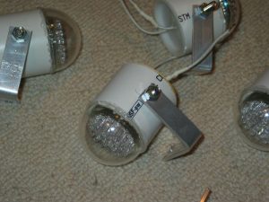 Now you just need to attach the L’s to your light fixtures. That’s what the second nut was for, above. Crank them tight enough so they won’t move around, and then dab on some Loctite to keep them from coming loose as you adjust them. Alternatively you could use a lock nut, but they’re more expensive <grin>
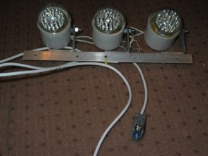
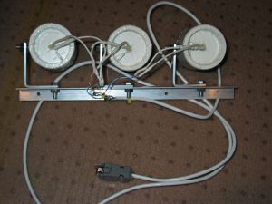
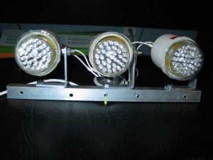
Somehow I got on a roll and forgot to take pictures of the next steps, so you’ll have to picture them in your mind as I describe them. You can also refer to the finished pictures, above.
Once you have all your fixtures assembled as per the above, you’ll want to test them. First of all, you probably forgot which color each fixture is. Secondly, if the thing doesn’t work, you’ll want to know now, before you get it wired up any further. I used a piece of colored electrical tape on the top of each fixture to indicate its color.
Next you’ll need to hook on the base to the upper part of the enclosure. If you’re feeling lucky, you could glue it. I wanted the ability to be able to get inside and work on these (e.g. if a bulb failed or wiggled out of its socket) so I simply used packing tape to hold the bottom to the top. This should be weatherproof enough, as long as they get inspected every year that the tape holds up.
Now you’ll need some angle stock. Again, I used aluminum, purchased at Home Depot. Each RGB fixture set will require 1 foot of aluminum angle stock. I cut it with the hacksaw, then brought it to the drill press, where I drilled 1/4″ holes on one side of the angle. One hole is centered, the other two go 2″ in from either side. On the other side of the angle, I drilled 5 5/16″ holes. Four of these will be used for mounting the fixture, and you can position them as you see fit. The fifth hole gets centered, and will be used to hold a wire-tie supporting our wiring harness.
Next, use 1/4″ hex bolts and nuts to assemble one Red, Green, and Blue fixture to your angle stock. As above, use Loctite to keep it all snug.
Now it’s time for the wiring. I used 6-conductor phone cable, which seems well-suited for this application. First of all you have a pair for each light. Secondly, it’s color coded pretty nicely: One pair is Blue/White-with-blue-stripe, One is Green/White-with-green-stripe, and one is Orange/White-with-orange-stripe. It doesn’t take too much of a stretch to see that you can use the Orange pair for Red, and the others for their correct color. Note that you could also use standard Ethernet wire and just ignore the brown pair, since phone wiring isn’t as prevalent as it was in 2008 when this was first written.
Polarity doesn’t matter for these LED’s, but for consistency, I connected the solid-color wire to the resistor bump, and the white/stripe wire to the other lead. These were soldered and covered with shrinkable tubing. I then used a couple of wire ties to neaten everything up, including one through the center hole mentioned above, for use as a strain relief.
The other end of the wire goes to your connector. When I first built these, I chose to use DB-9 connectors purchased from All Electronics. These are the same connectors that used to be commonly used for serial devices on PC’s, and, if you’re really old, Atari joysticks from the 80’s. The advantage to these connectors is that they’re cheap. The disadvantage is they’re a bit of a PITA to work with. In 2009, I purchased some new LED lights that used an RJ-45 (Ethernet-style) connector. Due to the pains working with the DB-9’s, creating new cables, downtime if one got damaged, etc, I decided to convert these lights to RJ-45 as well, so everything matched. Thankfully, relatively cheap RJ-45 jacks and plugs can be found on eBay and other sources. I highly recommend using the RJ-45’s if you use this, but the text below documents my original use of the DB-9’s.
The male connectors go on the lights, and the female on the controller. I made up some “extension cords” to the proper length as well.
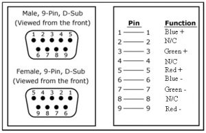 Here’s the pinouts I used for the DB-9 connectors I originally used. I obviously only needed 6 of the 9 pins. You can choose any pinout you like, as long as you know what it is and stick with it. It may be obvious, but when you’re soldering on the back of the DB-9 connectors, you actually want to refer to the diagram for the OTHER gender: e.g. you’re soldering a female connector from the back, the wires go in as if it’s a male connector.
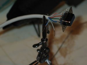 Here’s a pic I snapped of setting up one of these connectors. In this picture, I’ve soldered on the three solid wires but the striped ones have yet to be worked on. These DB-9 connectors have a little “scoop” for each wire. Unfortunately, it doesn’t actually hold the wire to help you solder — you have to sort of set the wire in it, hope it doesn’t spring out, then hit it with some solder to hold it in place forever. If you heat the pins too long, you’ll melt the connector and ruin it. I found that the males are more sensitive to this ,and you can help prevent it by plugging in a spare female connector to use as a heat-sink while you’re soldering. Also use a clean soldering tip, as dirty ones won’t pass heat properly and you’ll ruin a connector. Don’t ask me how I know this. Please do note that this picture is of a female connector that I was soldering up for the controller side of things, but other than the pinouts, the soldering process is the same.
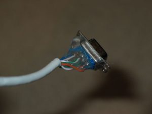 Once I had the connections soldered, and tested it with a multimeter, I injected the whole thing with hot glue. This should help protect the connections, keep them from shorting out, etc. I’m sure someone reading this who’s done these connections before will cringe at this, it seems to work. The connectors are cheap enough so that if one ever needs repair, you can snip it off and solder on a new one without worrying about cost. Buy some extra when you order them since shipping can be significant when you’re buying 30-cent connectors… Once this is all done, you use a DB-9 plastic hood to protect the whole thing, as shown in the pictures above and below.
The RJ-45 connectors that these were converted to work essentially the same way, except they have the advantage of being able to be installed with a punch-down tool instead of soldering. It’s much much simpler.
Above is a couple more views of the finished RGB light bank. Each light can be independently adjusted up/down and left-right. The bottom bracket can be mounted on a post, back of a display element, etc. The whole bank will easily plug into the controller channel.
Now that we know how the light-banks are constructed, we need something to control them. There’s a whole other page dealing with that, so click here and come along!

