Well now that we’ve created our banks of RGB LED Wash fixtures, we need a way to control them. Since the LED’s run on 12 volts, first of all we need an adequate power supply. Secondly, we need a controller board that can work with low-voltage DC, and finally, we need a weatherproof enclosure to house it all out in the elements.
The power supply is the easy part, if you have access to old PC’s. An old ATX power supply can power dozens of these lights all at the same time. The one I’m using is rated at 14A at 12V, which computes to 168 watts of power. Each of the MR-16 bulbs only takes 2 watts. I’m not sure how much power the controller board itself takes but as you can see, you can power a lot of lights with one such power supply.
I should have taken pictures of this part, but using an ATX power supply is actually really easy. First, cut off the plastic connectors from all the wires coming out of the supply. Next, cut off the zip-ties and sort the wires by color. For this project, we’re interested in only three colors: Green (of which there will be only one), yellow, and black. If you’re certain you want to dedicate this power supply to this project, you can open up the supply by removing the screws, and cut the wires off inside the supply. Make sure they don’t short out against anything. (Warning: do NOT have the supply plugged in while working inside, there are incredibly dangerous voltages inside). Otherwise, simply cap them off with electrical tape and ensure they don’t short with one another or anything else.
Next you want to short the green wire with one of the black wires. This forces the power supply to turn on when it’s plugged in. Insulate this connection.
Finally, you have two colors left: Black and Yellow. Yellow is +12V, and black is your ground/negative connection (0V).
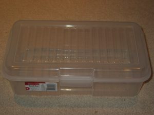
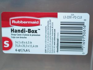
Now that you have a power supply, you need an enclosure. Finding a suitable enclosure was one of the hardest parts of this project for me. I would have preferred to use a ‘real’ enclosure, such as an electrical box or cable/satellite/telephone wiring enclosure such as we use for most of our other LOR controllers. But I wanted to house the power supply and controller board together, and none of the enclosures availble for less than a fortune I found would do that. I did want the enclosure to be as small as possible as well. It took me several shopping trips and having to buy and return two other enclosures before I found this one:
If you can’t find this box (I found it at Menards), or want to use something else, please note that the dimensions on most boxes are not only exterior dimensions, they’re measured from the widest possible spot — which for the width and depth means the plastic lip that extends about an inch on all sides. The bottom-inside dimensions can be as much as 3 inches smaller in each dimension. Not realizing this fact cost me a false enclosure (the other one was buying one that was significantly bigger than I needed — the opposite problem). This enclosure works pretty well (at least in concept): It holds both the power supply and controller board compactly, and has a hinged lid that snaps down.
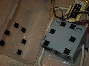 Anyway, my first step in assembling the enclosure was affixing the power supply. ATX supplies typically only have mounting capability from the fan side (which goes on the back of the PC enclosure). I wanted it affixed to the bottom. My solution? Velcro. It might seem silly, but it holds well, and allows me to pop out the supply easily. This latter point was important as I built the enclosure.
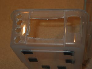 Next it was time to make some holes in the enclosure. I will be hanging it as a “cabinet” where the lid is really the door. So one of the sides becomes the “bottom”. The four holes will be for the individual lighting bank’s cords, the small square hole will be for power and controller input, and the large hole is for ventilation, as we will soon see.
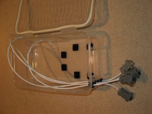 The next step is to hook up the lighting-bank output cables. I made up four cables with a female 9-pin D-sub connection (as mentioned on the LED Wash page). They are attached to the enclosure by some plastic strain-relief connectors I bought from All-Electronics a few years back. They are similar to these. A little hot-glue snugged them up since they’re really meant for SPT-1 wire. As mentoned on the other page, in 2009 I switched over to using RJ-45 jacks directly out of the bottom of the controller box (in place of the strain reliefs). The cords plug right into the bottom of teh box, and are sheltered from rain that way (I had to wrap the DB-9’s in plastic).
Next it’s time for the controller board. I’m using a Light-O-Rama CMB-16D for the controller board. Essentially, this is just like all of our other controllers, except this one controls low-voltage DC devices, whereas all of our other ones output 120V directly to each channel.
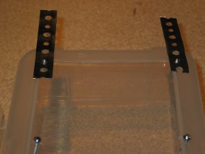 In order to mount the board to the enclosure, I marked the positions of the mounting holes, and drilled holes to insert four screws from the back. Drill the holes as small as possible and it will help keep the box raintight. Since I want to hang the enclosure, I used some perforated pipe strap as hangers attached to the topmost screws.
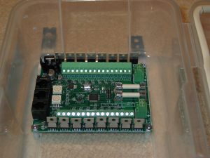 Use standoffs to hold the board up off the enclosure’s surface. Since this is a plastic enclosure, it isn’t absolutely necessary, but it will help keep the board cool and prevent any moisture that collects on the back surface from directly touching the board. I got these standoffs at Menards.
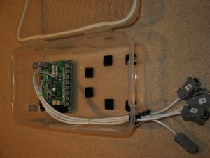 Now that the board is in place, you can wire the 9-pin harnesses to their proper channel. I simply went “R,G,B” in sequence for each lighting bank. I’m using only 12 of the 16 available channels at this time. Note how each connector is labeled with it’s proper “bank” number, each bank being a set of R,G,B LED lights. You’ll also note that I placed some rubber weather-stripping along the edge of the lid — just some additional insurance to keep it raintight.
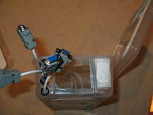 This picture shows how the bottom of the enclosure was finished. First, a piece of nylon window screen was cut and hot-glued around the large opening. This will keep critters out, and hopefully help keep any wind-driven snow out as well. The other opening was fitted with some white foam. This stuff is available at Michaels and comes in 9x12x1/4″ sheets. It was glued around the smaller opening, then slots cut in it to accommodate the power cable for the ATX supply, as well as the routing of the phone/Cat-5 communication cables to the LOR board.
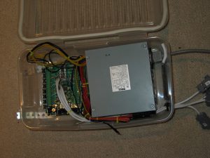 Sincethe power supply attaches with Velcro, you simply need to plug in the power cord and drop it into place. Then connect the yellow and black wires to the LOR board. I ran 2-3 wires of each type to each of the two ‘sides’ of the LOR board. For the load I’m running, a single wire-pair would have been more than sufficient, but I like to overbuild when cost isn’t an issue <grin>
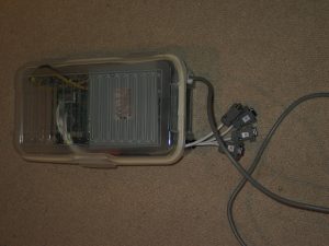 Voila, we’re done! Here’s the finished enclosure, all sealed up. Now all you need to do is plug in the various light banks. In my case, I’ll be placing them across the entire front of the house, so I’ll be making some “extension cords” with a male DB-9 on one end and a female on the other, sized for my application.
Hope this how-two was helpful and informative! If you made it this far, congrats and thanks for reading! Feel free to contact me with any questions, comments, or suggestions.

